One of the questions most frequently asked when someone is thinking about a personal design is — "What proportions should I use when designing a new model?"
A phrase used by Iain Rose in Silent Flight was ". . . use the figures to check the basic layout". This seems a little odd at first but is intentional. He suggests that one should not design from the figures — rather sketch the layout you like the look of and then check to see if the figures fall more or less within the values suggested.
The old adage remains true — "If it looks right, the chances are it's not far out!"
The first part is about the basic proportions, and it is common practice to quote all figures as fractions / multiples of the root chord (C).
The dot in the middle of the wing is the Aerodynamic Centre, which lies at about 30% of the Mean Aerodynamic Chord, about which, more a little later.
average wing chord = Cavg = (RC + TC)/2
wing area = WA = Cavg x S = S x (RC + TC)/2
tail area = TA = TS x (TRC + TTC)/2
wing area = WA = Cavg x S = S x (RC + TC)/2
tail area = TA = TS x (TRC + TTC)/2
Tail area should be about 10% of WAfor thermal soarers but up to 20% of WA for slope models.
Fin area should be 10 to 15% of WA.
Fin area should be 10 to 15% of WA.
measurement | multiple of C | ||
Nm | = | nose moment | 1,5 |
S slope | = | span (slope) | 8 to 10 |
S thermal | = | span (thermal) | 12 to 20 |
RC | = | root chord | |
TC | = | tip chord | |
Tm | = | tail moment | 2,5 to 3,0 |
TS | = | tail span | |
TTC | = | tail tip chord | |
TRC | = | tail root chord | |
As (one side) | = | aileron span | 0,2 to 0,5 of s |
AC | = | aileron chord | 0,2 |
* * * * *
The second part is about the Aerodynamic Centre (AC), also known as the Centre of Pressure or the Centre of Lift, which is the point at which all the lift forces are assumed to act.
"Balancing a model" involves adding lead so that the CG is close to 30% of the root chord (on a normal wing), which in reality means getting the CG close to the AC, so that these two opposing forces (weight down at CG and lift up at AC) balance,
not pitching the nose up ... CG behind AC —
or down ... CG in front of AC.
Working out the position of the AC thus shows where to balance a model.
So, just where is the Aerodynamic Centre?
It's close to (depends on section design) 30% of the MAC, which is half-way along a straight rectangular wing but closer to the root of a tapered wing — but how much closer?
This diagram and list of drawing instructions should enable you to find the Mean Aerodynamic Chord and hence the AC —
1 Draw the root chord length forward from the front end of the tip chord
2 Draw the tip chord length back from the back end of the root chord
3 Join the ends of these chord extensions
4 Join the midpoint of the tip chord to the midpoint of the root chord
5 Draw the MAC through the point where the two lines 3 and 4 intersect
6 The AC of this wing half is at 30% of the MAC.
A line drawn from the AC perpendicularly in to the fuselage centre line gives the CG position, which, it should be noted, may well still have to be trimmed slightly to suit pilot and model.
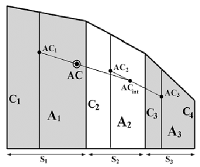
If the wing planform has a multiple taper, things are bit more complicated, but still follow the same basic pattern.
First, you find the AC of each panel using the method just described.
C1 = root chord
C2 = first intermediate chord
C3 = second intermediate chord
C4 = tip chord
S1 = span of first panel (between C1 and C2)
S2 = span of middle panel (C2to C3)
S3 = span of outer panel (C3to C4)
A1 = area between C1and C2 = S1 x (C1+C2)/2
A2 = area between C2and C3 = S2 x (C2+C3)/2
A3 = area between C3and C4 = S3 x (C3+C4)/2
Then you combine two of the panels, in this example the two outer ones, in a ratio determined by the contribution of their areas, to get an intermediate AC (ACint)
— where the ratio x/y = ratio of areas A3/A2
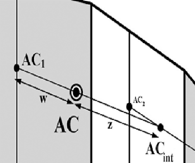
Finally, the inner panel AC1 is combined with the intermediate ACint in a similar fashion, by dividing the line between ACs according to the ratio of areas of A1and (A2 +A3).
— where ratio w/z = the ratio of areas (A2 + A3)/A1
As is often the case, a mathematical solution has a physical equivalent for those not too keen on maths.
If you cut out a precise scale plan of the wing from stiff card and balance it on a knife-edge parallel to the chord, the line on which it balances is the MAC, and the AC is 30% back from the leading edge.
A wooden dowel is easier to use as a "knife edge" as it can be rolled gently to achieve the balance point.


 Posted by


comment 0 Post a Comment
more_vert